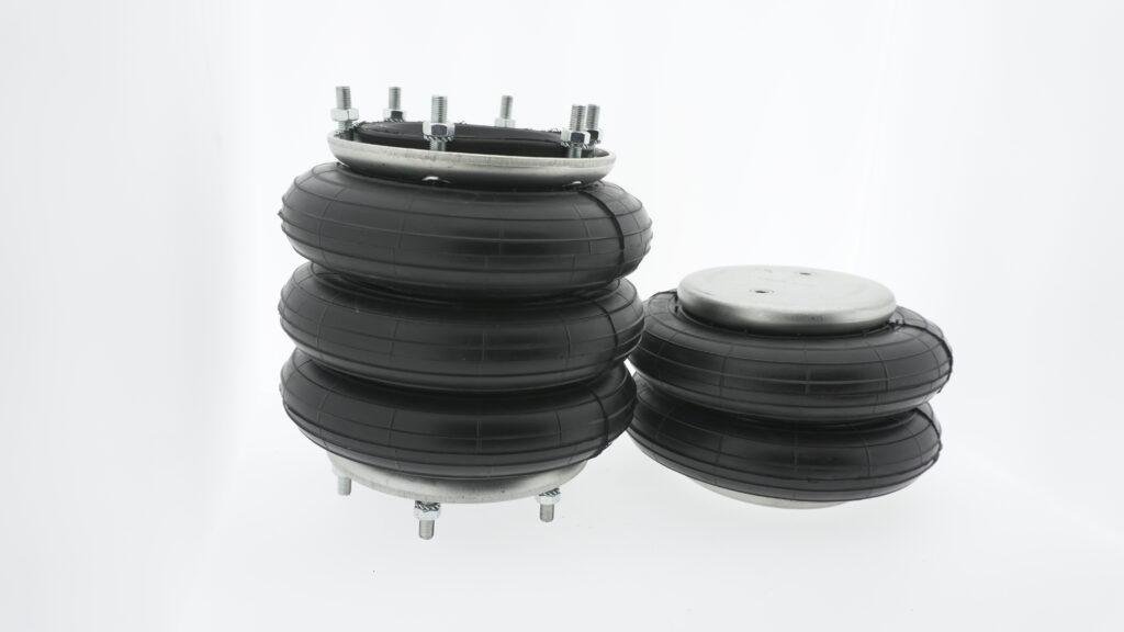
Conducting baseline vibration measurements
To evaluate air spring vibration isolation, we begin with baseline measurements. This provides a reference point to compare future results. We install accelerometers on both the machine and the isolated foundation. These sensors measure vibration amplitude and frequency before and after activation of the air spring system. Data is collected in real-time using a vibration analyzer. We plot vibration curves and analyze peaks across operating speeds. A reduction of more than 80% in amplitude indicates proper vibration isolation. We use FFT (Fast Fourier Transform) analysis to distinguish between structural and process-related noise. Without this, we risk misidentifying the air spring’s effectiveness. The test must be repeated at various load conditions. That includes idle, nominal, and maximum loads. All readings are documented. Differences in isolation performance at specific frequencies may suggest misalignment or improper inflation. Accurate testing begins with controlled, repeatable measurements using the correct equipment and methodology.
Evaluating transmissibility ratios under load
The key indicator of air spring vibration performance is the transmissibility ratio. This ratio compares transmitted to incoming vibration. We install the system on a vibration table and apply a controlled force. Accelerometers measure movement at both input and output points. The formula used is T = A₂ / A₁, where A₂ is output amplitude and A₁ is input. Ideal transmissibility for air bellows is below 0.2 at resonance frequencies. We test the unit under increasing loads to see how the ratio shifts. Changes indicate how well the air spring adapts under pressure. When transmissibility increases, isolation drops. That could mean the natural frequency is too close to the excitation frequency. Adjusting air pressure can correct this mismatch. We also test horizontal transmissibility for lateral forces. Effective vibration isolation should work in both axial and radial directions. This test ensures stability under real industrial conditions.
Testing dynamic response with impact hammers
To verify air spring vibration isolation, we use an impact hammer test. This evaluates dynamic response and damping characteristics. The hammer delivers a controlled impulse to the machine base. Accelerometers then record system response. The test reveals how quickly the air spring dampens energy. We analyze time-domain waveforms to check for resonance peaks and decay rate. A slow decay suggests insufficient damping. For high-precision systems, we aim for fast stabilization after impulse. The test is repeated in multiple directions to evaluate multi-axis behavior. We conduct tests before and after air pressure adjustment to measure impact. If response differs significantly, the unit may require recalibration. This method is ideal for comparing different air bellows or evaluating the same model under various settings. Results are used to fine-tune system design. For installations in high-vibration environments, these tests are essential. They confirm that the system reacts appropriately under unexpected forces.
Analyzing frequency shift and system tuning
A major part of air spring vibration testing is analyzing system resonance. We gradually increase excitation frequency and monitor response. When frequency input matches the natural frequency of the air spring, resonance occurs. We document the exact frequency at which this happens. Properly tuned systems place this point far from typical operating frequencies. If resonance is too close, we adjust air pressure or add damping elements. We compare measured natural frequency with design specs. Any deviation suggests aging rubber, internal damage, or incorrect inflation. Temperature shifts can also affect frequency. We run tests at ambient and elevated temperatures to check system stability. Proper vibration isolation means the system remains stable across environmental changes. We also use modal analysis to evaluate how the system deforms under vibration. The goal is to ensure consistent isolation over time, even with wear. Frequency shift analysis helps validate the long-term performance of air bellows.
Using simulation models to validate real-world data
Modern air spring vibration testing includes digital simulation. We create a finite element model (FEM) of the system using known parameters. These include geometry, material stiffness, and load ranges. Simulations predict how the air spring will react to external vibration. We compare simulated results with test data from the field. Differences reveal calibration errors or real-world complexities not captured by the model. Simulation also helps optimize new installations by testing virtual layouts. We simulate load steps, temperature effects, and lateral impacts. Real-time adjustments in the simulation allow faster testing iterations. Simulation also aids in training new engineers, helping them understand how air bellows respond dynamically. This integration of physical and digital validation improves design reliability. Simulation data is also used to set benchmark values for production quality checks. By combining real and simulated testing, we ensure maximum performance from every air spring installation.
