
Avoiding errors in air spring installation is critical for ensuring durability, performance, and safety in high-precision environments. We frequently encounter failures not from product defects but due to incorrect setup, misalignment, or pressure mismanagement. Many technical springs, especially rubber-based actuators, rely on exact design height, natural frequency, and stroke capacity to function properly. A common issue is ignoring the force range at 7 bar, which for some models reaches over 248 kN. Additionally, installation height must match the specified minimum and maximum design parameters to avoid stress concentration. Always consult the air inlet thread size, plate material (aluminum, steel, or AISI-304 stainless), and convolution type. These determine performance boundaries under load. We recommend that installers validate air line pressure, material composition, and mounting geometry before commissioning the system. Starting with a comprehensive understanding of specifications reduces long-term maintenance and failure risks in static and dynamic applications.
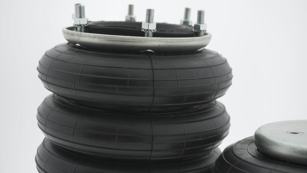
Failing to check mounting compatibility
One of the most frequent installation mistakes is overlooking mounting compatibility between the system and the air bellow. Each unit includes specific end closure types—crimped, bead ring, or dismountable—which must match corresponding hardware. Misalignment of mounting studs, bolt patterns, or port dimensions causes early-stage stress and air leakage. Air bellows may come with G1/4”, G3/4”, or G1/2” air inlets, so proper matching is essential. For example, triple convolution designs can reach a stroke of 375 mm and support loads over 75 kN. Mounting surfaces must be perfectly parallel and flat to prevent twisting. Some designs also allow for blind nuts in the end plates, which should correspond with thread specs like M8x1.25 or M10x1.5. A mismatch here not only disrupts pressurization but also threatens rubber integrity. Always verify interface details from technical data sheets. Compatibility is not optional—it’s fundamental for structural integrity and pressure stability.
Over-tightening of mounting bolts
Over-tightening mounting bolts is a serious but avoidable mistake during air spring installation. Excessive torque on bead plates or flanged ends compresses the rubber convolutions, causing internal delamination or cracking. Many air bellows use electro-galvanized or stainless-steel plates rated for specific fastening torques. For example, M10 bolts commonly require torque values no greater than 40 Nm under dynamic load conditions. Variations in bolt length, stud placement, or blind nut depth affect load distribution across the seal interface. An uneven seal allows air to escape or pressure to concentrate asymmetrically, increasing vibration and wear. We strongly advise using a calibrated torque wrench and following defined torque specifications listed per convolution type and diameter size. Misapplication of torque also reduces natural frequency stability, especially in high-cycle isolator use. Distribute pressure evenly across all fasteners. Proper bolt tension avoids deformation and ensures repeatable performance throughout the spring’s operating range.
Using contaminated air supply
Using contaminated air during air spring installation introduces long-term performance risks that often go unnoticed until failure occurs. Compressed air, when unfiltered, often contains oil vapor, moisture, or particulates, which accelerate rubber degradation. This is especially problematic for multi-ply bellows operating under 12 bar pressure, where internal cleanliness is vital. Degradation occurs at the inner rubber cover, impacting the reinforcement fabric plies sandwiched between rubber layers. We recommend installing coalescing filters, desiccant dryers, and particulate traps to protect internal volumes. In cases where media includes water or oil, the use of AISI-304 or AISI-316L stainless steel end plates is mandatory. Without this, internal rust compromises pressure retention and stroke reliability. Air springs are also sensitive to ozone exposure, which degrades outer layers if lubricated air circulates through unshielded environments. Clean air supports consistent isolation and force output. Filtering and controlling air quality should be part of every installation procedure.
Skipping pre-installation inspection
Skipping a visual and tactile inspection before air spring installation is one of the most overlooked risks in industrial setups. Air bellows stored incorrectly may exhibit surface cracking, rubber hardening, or improper bonding of steel and elastomer layers. Storage guidelines per ISO 2230 require conditions free of UV light, ozone, and temperature extremes (between -10 °C and +25 °C preferred). Physical damage, like abrasions on outer rubber or warped bead rings, directly compromises pressure capacity. For example, a minor dent in a bead ring closure can create a non-uniform seal, leading to leaks under load. Inspect bolt threads, plate welds, and rubber alignment carefully. Pay attention to markings and specification labels to confirm model type and pressure rating. Even slight deviations from original specs—such as on design height, typically ranging between 50 mm and 140 mm—can result in misfit installations. Don’t risk failure—inspect thoroughly before mounting.
Incorrect pressurization during setup
Incorrect pressurization during air spring installation is a leading cause of premature failure and performance degradation. Every bellow has a defined maximum operating pressure: 8 bar for standard builds, and 12 bar for four-ply high-strength constructions. Over-pressurizing distorts internal structure, while under-pressurizing compromises height regulation and load stability. For instance, a double convolution 16″ bellow is designed for 265 mm stroke and 73 kN force at 7 bar. Deviating from this destabilizes its natural frequency, often calibrated between 1.2 Hz and 3.0 Hz. Never pressurize without using a calibrated gauge. Ensure no leaks exist at the G-thread air inlets, and validate alignment at design height using laser or manual measuring tools. We advise against pressurizing under load unless the mounting surfaces are fully secured. Consider using overpressure safety valves and regulators to maintain consistent supply pressure. Stable and safe pressurization enhances product life and guarantees performance under varying industrial conditions.
Misalignment of mounting surfaces
Misalignment of mounting surfaces causes uneven stress distribution and early wear in air bellows, regardless of convolution type or end closure. Air springs must be mounted perpendicular to the load axis, ensuring proper pressure transfer. Even a 5° misalignment between top and bottom plates shifts load paths into the rubber sidewalls, leading to structural fatigue. Many units, especially larger triple convolutions with external diameters up to 950 mm, are susceptible to torsion when not correctly aligned. Use digital inclinometers, laser guides, or precision machined surfaces to ensure perfect alignment. Never correct tilt by overtightening fasteners or adding uneven shims; this distorts the convolution profile. Confirm that stud holes on end plates match fixture geometry. Any mounting error reduces the effectiveness of vibration isolation and may alter stroke characteristics. For bellows designed with tilt capabilities up to 25°, let the product flex naturally within its limits—don’t impose angle compensation through forced installation.
Not accounting for dynamic movement
Dynamic applications often expose flaws in the air spring installation when movement patterns aren’t properly considered. Bellows function across axial strokes, angular tilts, and lateral offsets, but these movements must stay within rated tolerances. For example, some designs support lateral misalignment up to 30 mm, while others are limited to ±5 mm. Ignoring this results in rubber tearing at the convolution junctions, especially near central rings. During installation, verify the maximum stroke, which can reach 400 mm in large triple convolutions, and ensure that no part of the bellows is mechanically constrained. Check system for axial preloading or external misalignments introduced by rigid connections. Bellows with natural frequencies under 2 Hz are highly sensitive to movement restrictions. Incorporate flexible couplings or guidance rails where needed. If misalignment or lateral shift occurs under pressure cycling, the spring wears prematurely. Accommodating dynamic motion safeguards both the air spring and surrounding equipment structure.
Improper selection of end closures
Choosing the wrong end closure configuration compromises sealing efficiency, mechanical compatibility, and pressure performance. Three designs exist: dismountable, bead ring, and crimped. Dismountables use top/bottom plates with clamping bead rings, ideal for systems requiring frequent maintenance. Bead ring types are semi-fixed, using socket-head or countersunk fasteners for integration. Crimped closures, common in high-pressure setups, are non-removable and feature blind nut fixation. Using the wrong closure introduces risks like non-uniform bolt tension, air leakage, or misaligned stroke paths. For instance, mounting a crimped design on a system expecting lateral access leads to misfit. Crimped bellows support higher loads, often exceeding 150 kN, but require exact alignment. Mismatches also affect air port locations, which vary from G1/4″ to G3/4″, depending on type. Always review closure compatibility with system layout and required maintenance frequency. The right closure enhances integrity, isolation, and longevity. Poor closure selection often leads to catastrophic operational failure.
Failing to secure air lines properly
Unsecured air lines introduce operational instability, leak risks, and component interference during system operation. Air bellows are highly responsive to air flow direction, inlet torque, and port sealing. Air lines must be attached using properly rated threaded fittings, commonly BSP or NPT, with thread sealant applied sparingly. Air inlets like G1/4″, G1/2″, and G3/4″ have specific torque ranges that must not be exceeded. Lines should be routed to avoid vibration sources, abrasion points, and thermal exposure. Use hose clips, braided sleeves, and anchor brackets to stabilize routes. Movement during actuation can cause flexing at the joint, leading to inlet thread wear or air bursts. Each hose should have a strain relief loop to absorb motion. Inspect for sharp bends or contact with moving parts. Consider quick-disconnects or flexible adapters for easy maintenance. A well-secured line extends equipment life and avoids pressure drops that affect bellow performance.
Disregarding isolation performance factors
One major error during air spring installation is disregarding isolation performance variables like load balance, pressure synchronization, and height leveling. Isolation efficiency depends on matching the natural frequency of the bellow to the equipment it supports. Some units reach below 1.4 Hz, offering near-total vibration absorption. However, installing multiple bellows at inconsistent heights leads to unbalanced loads and phase interference. The system becomes dynamically unstable, negating the benefit of rubber-based damping. Always install individual regulators or balancing valves when using more than one air spring. Adjust each bellow to its design height, which ranges from 50 mm to 140 mm, depending on model and configuration. For high-stability setups, include height sensors and feedback controllers. Without these, weight shifts can over-compress a unit, pushing it beyond its force range, which peaks near 450 kN for some versions. Isolation is only effective when system symmetry and pressure parity are maintained across all support points.